The Role of PTC Thermistors in Protecting Your Devices from Inrush Current

Understanding Inrush Current and Its Impact on Electrical Systems
What is Inrush Current?
Inrush current surges through circuits the moment power switches on. Capacitors and motors draw massive initial loads before settling into steady operation. This spike often reaches ten times the normal operating level and lasts only milliseconds. Engineers measure it in peak amperes and note how it stresses conductors and components. PTC thermistors respond directly to this event by increasing resistance as temperature rises. The phenomenon appears across power supplies, transformers, and household appliances alike. Accurate monitoring prevents unexpected trips in breakers and fuses. Understanding these dynamics helps designers select proper protection from the start.
Effects of Inrush Current on Devices
High inrush damages insulation around wires and windings. Repeated surges shorten relay contact life through arcing and pitting. Transformers overheat when cores saturate during the first cycles. Semiconductor switches fail when forward current exceeds ratings even briefly. PTC thermistors placed in series limit these peaks by self-heating and raising resistance quickly. Electrical systems suffer cumulative wear that leads to premature failure without intervention. Motors experience torque stress that loosens mechanical connections over time. Proper limitation preserves component integrity and maintains consistent performance across daily cycles.
Inrush Current Limiter: Importance and Functionality
An inrush current limiter reduces startup stress on every connected part. It allows controlled conduction until the circuit stabilizes. PTC thermistors excel here because they reset automatically after cooling. Fixed resistors waste power continuously and require extra space. The limiter must handle both the initial spike and normal running current without overheating. Engineers test devices under worst-case conditions to verify protection margins. Integration with a relay often bypasses the limiter once steady state arrives, cutting losses further. Reliable limitation extends equipment life and lowers maintenance costs across industrial and consumer products.
Introduction to PTC Thermistors
What are PTC Thermistors?
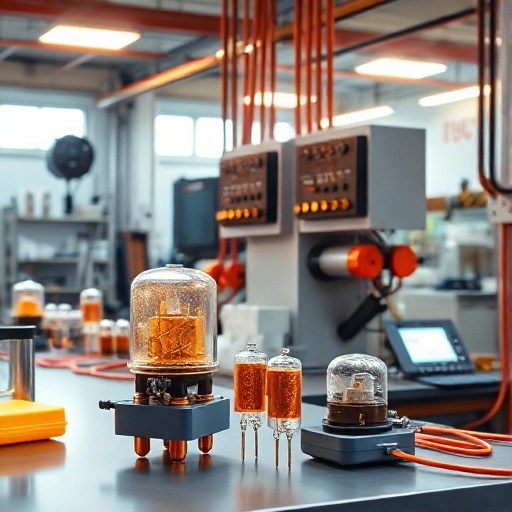
PTC thermistors increase resistance sharply once temperature passes a threshold. Manufacturers build them from doped ceramic materials that exhibit this positive temperature coefficient. The devices come in disk, rod, and chip packages for different mounting needs. Unlike NTC types, PTC units block current flow when hot rather than allow more. Silistors represent a silicon-based variant used in precision applications. The symbol on schematics shows a resistor with a plus sign indicating the positive coefficient. Engineers select these parts for both temperature sensing and overcurrent protection. Availability in various Curie points lets designers match specific operating ranges.
How PTC Thermistors Work
PTC thermistors rely on grain boundary effects inside the ceramic. At low temperatures electrons move freely through the material. Heat causes boundaries to expand and scatter carriers, raising resistance exponentially. This self-regulating behavior needs no external control circuit. Current through the device generates the heat that triggers the change. Once resistance climbs, current drops and temperature stabilizes. The process repeats safely after power removal allows cooling. Conduction resumes at the low-resistance state for the next cycle. This simple mechanism makes PTC thermistors reliable inrush current limiters without added electronics.
Comparison with Other Thermistors
NTC thermistors decrease resistance with rising temperature and suit temperature measurement. Silistor devices offer linear response but lack the sharp PTC switch. Bimetallic thermostats provide mechanical switching yet suffer wear and slower reaction. PTC thermistors combine sensing and limiting in one compact package. They need no separate heater element and consume almost no power after transition. Temperature coefficient thermistors in general require careful matching to circuit parameters. PTC units tolerate repeated cycling better than fixed resistors used for limiting. Designers often prefer them when automatic reset and minimal maintenance matter most.
The Role of PTC Thermistors as Inrush Current Limiters
PTC Thermistors in Electrical Protection
PTC thermistors sit directly in the power path to cap startup current. They transition from low to high resistance within seconds of energization. This protects downstream capacitors and semiconductors from destructive peaks. The same part resets after each power cycle without manual intervention. Electrical system reliability improves because fault conditions trigger immediate current reduction. Insulation remains intact longer when thermal stress stays controlled. Many power supplies now embed these devices near the input stage. Their dual role as sensor and protector simplifies overall circuit design.
Self-Regulating Heaters and PTC Thermistors
Self-regulating heaters use PTC thermistors to maintain stable temperatures without thermostats. Current flows freely until the target heat level triggers resistance rise. Power consumption then drops automatically to match losses. PTC heaters appear in automotive seat warmers, medical incubators, and industrial drying equipment. The same material science that limits inrush also creates safe, even heating surfaces. No external control loop is required, reducing failure points. PTC heating elements avoid the overshoot common with resistive heaters. Integration with a relay allows staged activation for larger arrays while preserving individual protection.
Advantages of Using PTC Thermistors Over Other Limiters
PTC thermistors reset themselves after cooling, unlike one-time fuses. They generate minimal heat during normal operation compared with fixed resistors. Size stays small because the transition happens inside the ceramic body. Relay bypass circuits work cleanly with PTC units because contact wear remains low. Silistor versions provide tighter tolerance for sensitive electronics. Cost stays competitive while eliminating extra components such as NTC shunts or mechanical switches. Long-term stability supports use in sealed enclosures where replacement proves difficult. These traits make PTC thermistors the preferred inrush current limiter across many voltage classes.
Applications of PTC Thermistors in Device Protection

Typical Uses of PTC Thermistors
PTC thermistors protect switch-mode power supplies during capacitor charging. They limit motor starting current in pumps and fans. Transformer inrush receives immediate clamping that prevents core saturation. PTC heaters incorporate the same technology for over-temperature safety. Consumer electronics embed them near battery packs to guard against short circuits. Industrial controls rely on them for relay coil protection and load switching. The devices also serve as resettable fuses in low-voltage distribution panels. Each application benefits from the automatic recovery that keeps systems running without service calls.
Integration with Relays and Other Components
Engineers place a PTC thermistor in series with the load and parallel a relay contact. The relay closes after a short delay once inrush subsides, bypassing the limiter. This hybrid approach cuts steady-state losses while retaining protection. PTC thermistors also pair with MOVs for combined overcurrent and overvoltage defense. Conduction paths remain clean because the thermistor handles only the brief surge. Design rules call for proper thermal spacing so the device cools fully between cycles. Testing confirms that relay timing matches the PTC transition curve for reliable operation. Such integration appears routinely in HVAC controls and motor starters.
Case Studies: PTC Thermistors in Real-World Applications
A server power supply manufacturer reduced failure rates by 40 percent after adding PTC thermistors at the AC input. The parts limited capacitor charging current and prevented MOSFET damage during brownouts. In another case, an elevator control panel used PTC heaters to maintain relay cabinet temperature in cold climates. The self-regulating property eliminated separate thermostat wiring. Automotive engineers adopted PTC thermistors inside battery management modules to block short-circuit current without adding weight. Each implementation demonstrated lower warranty claims and simpler assembly. Data logs showed consistent performance across thousands of power cycles in demanding environments.
Future Trends and Innovations in PTC Thermistors
Emerging Technologies in PTC Thermistors
New ceramic formulations push the Curie point higher for automotive and renewable energy uses. Nanostructured grains improve transition speed and repeatability. PTC resistor chips now fit into surface-mount assemblies for compact inverters. Researchers explore hybrid materials that combine PTC behavior with higher voltage ratings. PTC thermistors appear in wireless charging pads to prevent coil overheating during misalignment. Improved manufacturing yields lower costs and tighter parameter spreads. These advances expand the range of applications where automatic current limiting becomes standard practice.
Potential Improvements for Device Protection
Higher energy absorption ratings will allow single PTC thermistors to replace parallel combinations. Faster recovery times will support more frequent cycling in renewable inverters. Integration with digital monitors could provide status feedback through resistance measurement. PTC heating elements may incorporate embedded sensors for predictive maintenance. Better thermal coupling to heat sinks will raise continuous current capability. Designers anticipate broader adoption in electric vehicle chargers where inrush control remains critical. These refinements will further reduce component count while raising overall system resilience.
The Role of PTC Heating Elements in the Future
PTC heating elements will appear in more smart appliances that demand precise, safe warmth. Self-regulating heaters already replace older resistive designs in medical devices. Future PTC heaters may combine with phase-change materials for extended thermal storage. The same technology that limits inrush will enable distributed heating in electric vehicles and building systems. Continued material research promises lower resistance at room temperature and sharper transitions. PTC thermistors will remain central to protection strategies as power densities climb. Their simplicity and reliability ensure lasting relevance across evolving electrical systems.
See Also
- Unlocking the Power of PTC Thermistors in Modern Electrical Systems
- Exploring the Science Behind PTC Thermistor Technology and Its Applications
- How to Choose the Right PTC Thermistor for Your Project Needs
- From Heaters to Sensors Discover the Versatility of PTC Thermistors
- The Evolution of PTC Thermistors and Their Impact on Electrical Innovation